
1. Transmission Frequency & Antenna Design:
1.2MHz and 500KHz Transmission Frequencies: The tool employs dual-frequency transmission.
1.2MHz (High Frequency): Offers relatively higher resolution, is more sensitive to the formation near the borehole (invaded zone) and thin beds, but has a shallower depth of investigation (stronger skin effect). Suitable for identifying thin beds, fractures, and borehole irregularities.
500KHz (Low Frequency): Has relatively lower resolution but a deeper depth of investigation (weaker skin effect), is less affected by the borehole and invaded zone, and better reflects the resistivity of the virgin formation. Suitable for detecting true formation resistivity.
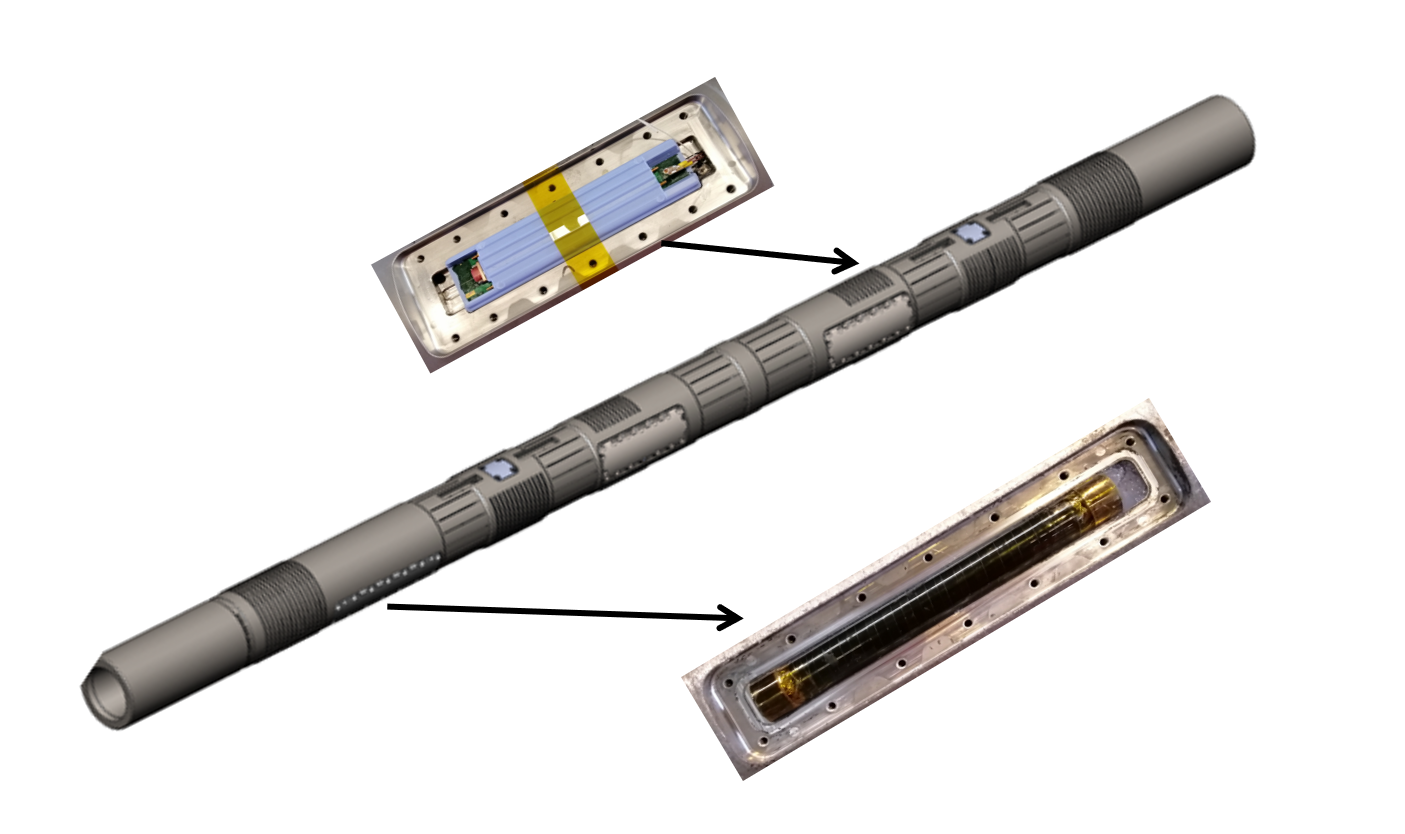
Four-Transmitter Dual-Receiver Antenna Design: This is the core enabling multiple depths of investigation (DOI) and azimuthal measurement.
Four Transmitters: Four transmitting coils (typically symmetrically distributed at different azimuths or depths) can be combined to excite electromagnetic fields with different source spacings and directions.
Two Receivers: Two receiving coils (typically spaced a fixed distance apart) measure differences in the electromagnetic field (amplitude and phase) for various transmitter-receiver combinations.
Function: This design allows the tool to simultaneously obtain measurements for multiple source spacings (from short to long) and different azimuths, forming the basis for Parameter 2 (8 curves at different depths) and azimuthal information.
2. Resistivity Curves:
8 Curves of Symmetrically Compensated Resistivity at Different Depths: This is one of the tool's primary outputs.
Different Depths: Utilizes multiple source spacing combinations (e.g., extra-short, short, medium, long) generated by the "four-transmitter dual-receiver" design. Each spacing corresponds to a different radial depth of investigation (DOI). Longer spacing provides deeper DOI.
Symmetrical Compensation: Refers to the use of compensation measurement techniques (e.g., dual-transmitter compensation, dual-receiver compensation) aimed at eliminating or reducing effects from instrument electronic drift, temperature variations, and certain borehole irregularities (e.g., ellipticity), significantly enhancing measurement accuracy and stability. This is the key technology enabling Parameter 3 (stable, true, reliable).
8 Curves: This is a specific indicator, meaning the tool provides resistivity measurements for 8 different radial depths of investigation. These curves aid in analyzing the mud filtrate invasion profile (flushed zone, transition zone, virgin zone) and determining true formation resistivity.
3. Data Quality Assurance:
Field-Proven Application Ensuring Stable, True, and Reliable Resistivity Measurements: This emphasizes the tool's engineering maturity and field adaptability.
Stable: Tool design (e.g., symmetrical compensation) and manufacturing processes ensure data repeatability and consistency during prolonged operation in complex downhole environments (high temperature, high pressure, vibration).
True: Through multiple-depth measurements, compensation techniques, and appropriate frequency selection, the data strives to accurately reflect formation electrical properties, minimizing environmental interference.
Reliable: Indicates stable tool performance, low failure rates, and high data credibility.
4. Real-Time Transmission:
Real-Time Transmission Typically Includes 2 Curves (Configurable per Client Requirements): Refers to the transmission of key data to the surface in real-time via mud pulse telemetry during Logging While Drilling (LWD) operations.
Typically 2 Curves: Due to limited telemetry bandwidth, the most critical resistivity curves representing different DOIs are prioritized (e.g., one shallow DOI high-frequency curve for geosteering/thin bed identification, one deep DOI low-frequency curve for formation evaluation).
Configurable per Client Requirements: Demonstrates tool flexibility. Based on specific operational objectives and downhole conditions, users can select which two curves are most useful for transmission (e.g., potentially prioritizing phase resistivity in oil-based mud).
5. Long-Spacing Low-Frequency Phase-Derived Resistivity:
Long Spacing: Indicates a large distance between transmitter(s) and receiver(s), providing a deep depth of investigation (DOI).
Low Frequency (500KHz): As mentioned, low frequency inherently provides deeper DOI and is less affected by dielectric effects.
Phase-Derived Curve: Refers to resistivity calculated primarily from the phase difference of the received electromagnetic wave. Phase-derived resistivity is generally more sensitive in resistive formations and less affected by borehole irregularities than amplitude-derived resistivity.
Combined Advantage: The combination of Long Spacing + Low Frequency + Phase Measurement provides the tool's deepest DOI and largest radial measurement range. This makes this curve least affected by the borehole and invaded zone, best approximating and reflecting the true resistivity (Rt) of the virgin formation far from the borehole. It is a key basis for evaluating formation fluid properties (oil, gas, water).
6. Short-Spacing High-Frequency Phase-Derived Resistivity:
Short Spacing: Indicates a small distance between transmitter(s) and receiver(s), providing a shallow depth of investigation (DOI), sensitive to the formation near the borehole.
High Frequency (1.2MHz): As mentioned, high frequency provides higher resolution.
Phase-Derived Curve: Also utilizes phase difference, sensitive to resistive formations and less affected by the borehole.
Application Advantages:
High Resolution & Shallow DOI: Clearly identifies thin beds (e.g., interbeds), fractures (high-conductivity fractures appear as low-resistivity anomalies), and lithological boundaries.
Reflecting Reservoir Boundaries: In horizontal well geosteering, the short-spacing high-frequency curve reacts sensitively to formation changes near the bit (e.g., drilling out of the reservoir into surrounding rock/water zone), making it a key indicator for staying within the target reservoir.
Identifying Interbeds: Provides good resolution for identifying thin, non-permeable interbeds (e.g., shale interbeds, calcareous interbeds) within the reservoir interval.
Summary and Advantages
The main technical advantages and features of this Resistivity & Azimuthal Gamma tool lie in:
1. Multi-Frequency, Multi-Spacing, Multi-Depth: Through dual frequencies (1.2MHz, 500KHz) and the "four-transmitter dual-receiver" design, it provides up to 8 compensated resistivity curves at different radial depths of investigation, comprehensively characterizing the invasion profile for more accurate determination of true formation resistivity.
2. Deep Investigation Capability: The long-spacing low-frequency phase-derived resistivity curve provides the deepest DOI, approximating virgin formation resistivity (Rt), which is core to reservoir evaluation.
3. High Resolution and Boundary Identification: The short-spacing high-frequency phase-derived resistivity curve offers high resolution and sensitivity to thin beds, fractures, interbeds, and formation boundaries, making it crucial for geosteering and detailed reservoir characterization.
4. Data Quality and Stability: Emphasis on symmetrical compensation technology and engineering implementation ensures stable, true, and reliable field data.
5. Real-Time Geosteering Flexibility: Supports real-time transmission of key resistivity curves, configurable as needed, meeting geosteering requirements.
6. Azimuthal Information: The "four-transmitter dual-receiver" structure typically implies azimuthal measurement capability (although "imaging" isn't explicitly stated in the parameters, the "Azimuthal Gamma" name suggests it), providing formation resistivity and natural gamma information around the borehole circumference. This is used for identifying fracture orientation, formation anisotropy, and determining bit position relative to formation boundaries. (The provided parameters focus primarily on resistivity; specific parameters for the azimuthal gamma component are not listed, but it is an important part of the tool, providing lithological and azimuthal information).
In summary, this is an advanced, fully-featured LWD Azimuthal Resistivity Imaging tool. Its design goals are clear: to provide high-quality resistivity data at multiple depths of investigation (deep, medium, shallow) in complex drilling environments (especially high-angle/horizontal wells), coupled with azimuthal detection capability. This enables precise identification of formation boundaries, fractures, and thin interbeds, accurate evaluation of true formation resistivity, and delivers powerful real-time and post-drilling interpretation support for geosteering and reservoir evaluation.